Jandakot (YPJT)
Positions
| Name | Callsign | Frequency | Login ID |
|---|---|---|---|
| Jandakot ADC West | Jandakot Tower | 118.100 | JT_TWR |
| Jandakot ADC (Circuit) | Jandakot Tower | 119.400 | JT-C_TWR |
| Jandakot SMC | Jandakot Ground | 124.300 | JT_GND |
| Jandakot ATIS | 128.650 | YPJT_ATIS |
Non-Standard Positions
Non-standard positions may only be used in accordance with VATPAC Air Traffic Services Policy.
Approval must be sought from the bolded parent position prior to opening a Non-Standard Position, unless NOTAMs indicate otherwise (eg, for events).
Airspace
JT ADC is responsible for the Class D airspace in the JT CTR SFC to A015.
Dual ADC Operations
When Jandakot ADC (Circuit) is online, responsibility for the Runway, Circuit, and Airspace is divided between the two ADC controllers.
ADC West takes responsibility for the North-West Runway, Circuit and Airspace (Runway 06L/24R), and the entire JT CTR at A015.
ADC (Circuit) takes responsibility for the South-East Runway, Circuit and Airspace (Runway 06R/24L) at or below A010.
ADC (Circuit) is not permitted online when Single Runway Operations are in use.
Refer to the ATIS section for information on ATIS formatting when ADC East is online.
Airspace
Airspace Ownership when ADC East is online, is:
- At
A015; owned entirely by ADC West - At or below
A010; split between ADC Circuit/West down the middle of the 06L/24R and 06R/24L extended centrelines.
VFR Operations
Arrivals
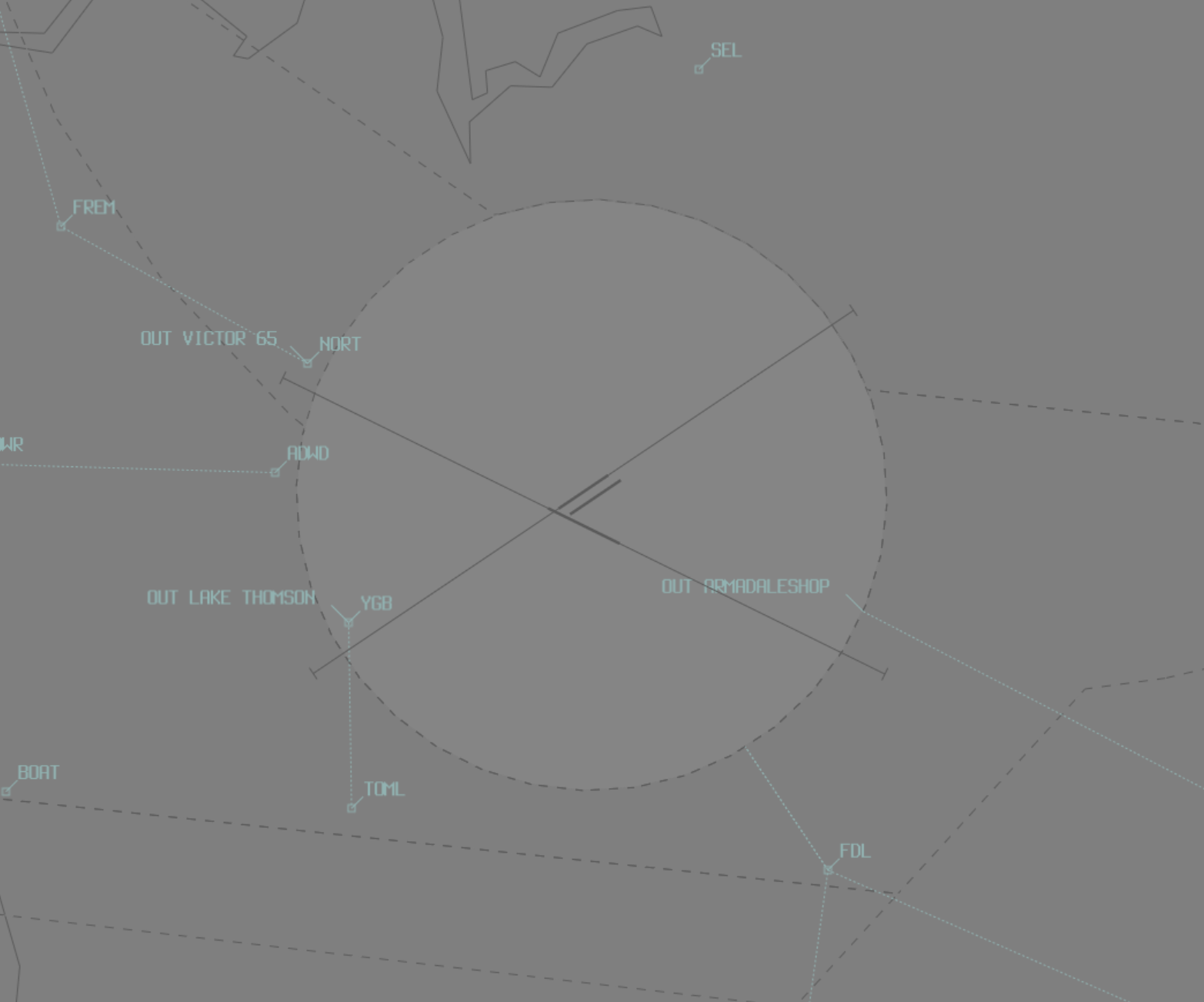
VFR aircraft will report inbound at BOAT, POWR, OAKF or RUSS at A015. JT ADC shall instruct aircraft to maintain A015 and report again at ADWD when inbound from BOAT or POWR, or FDL when inbound from OAKF or RUSS.
Aircraft should then be instructed to join the circuit as below:
| VFR Approach Point | RWYs 06 | RWYs 24 | RWY 12 | RWY 30 |
|---|---|---|---|---|
| ADWD | "Join base runway 06L" | "Join right downwind runway 24R, maintain A015", until the aircraft are clear of RWY 24R departures via Fiona Stanley Hospital and FREM, then "Cleared Visual Approach" | "Join final runway 12" | "Join downwind ruwnay 30, maintain A015", until the aircraft is clear of RWY 30 departures via YGB, then "Cleared Visual Approach" |
| FDL | "Join downwind runway 06L, maintain A015". Aircraft should fly overhead the airfield between the control tower and the upwind end of the runway and join the circuit. Once established in the circuit, "Cleared visual approach" | "Join right downwind runway 24R, maintain A015". Aircraft should fly overhead the airfield between the control tower and the upwind end of the runway and join the circuit. Once established in the circuit, "Cleared visual approach" | "Join right downwind runway 12" | "Join final runway 30" |
All aircraft will arrive on runway 06L/24R or 12/30.
Note
Circuit joining instructions given without an assigned altitude imply clearance to conduct the visual approach. There is no need to clear these aircraft for a visual approach.
Departures
VFR aircraft shall generally depart the zone on an extended circuit leg at A010, except for those tracking via FREM.
Aircraft departing via FREM shall track from the circuit to Fiona Stanley Hospital, then climb to A015 and track to FREM.
Note
A takeoff clearance constitutes a clearance to depart the zone by extending the pilot's requested leg of the circuit. Aircraft departing the zone into class G airspace will transfer to area frequency upon leaving the zone, no explicit frequency transfer is given to these aircraft.
Helicopter Operations
General
Unless otherwise depicted in the ERSA FAC YPJT, all helicopters must comply with fixed wing procedures.
Circuits
Circuits are conducted within the lateral confines of the fixed-wing circuit at A008, in the same direction as the current runway config. The termination point of the circuit is the Main Pad.
Runway Modes
Preferred Runway Modes
Winds must always be considered for Runway modes (Crosswind <20kts, Tailwind <5kts), however the order of preference is as follows:
| Priority - Mode | Arrivals | Departures | Circuits |
|---|---|---|---|
| =1 - 06 PROPS | 06L | 06R (DEPS VIA SHOP) & 06L (ALL OTHER DEPS) | 06R |
| =1 - 24 PROPS | 24R | 24L (DEPS VIA SHOP) & 24R (ALL OTHER DEPS) | 24L |
| =2 - 12 only | 12 | 12 | 12 |
| =2 - 30 only | 30 | 30 | 30 |
The ATIS shall be updated to reflect the use of each runway.
Night Operational Restrictions
Runway 06R/24L is unlit, and cannot be used at night.
Circuits
Circuits shall be flown at A010.
| Runway | Day | Night |
|---|---|---|
| 06L | Left | Right |
| 06R | Right | - |
| 24L | Left | - |
| 24R | Right | Left |
| 12 | Left | Left |
| 30 | Left | Left |
SID Selection
Aircraft shall be assigned the appropriate SID according to their direction of travel.
| Direction | SID |
|---|---|
| North and West | ISPET^ |
| East | SCARP^ |
| South and West | TONEG |
Note
^ The ISPET and SCARP SIDs include visual maneuvres when departing Runway 06L is in use. The ISPET SID also includes a visual maneuvres for aircraft departing Runway 12. When the cloud base is at or below A007, the TONEG SID should be assigned in lieu of these SIDs when departing an affected runway.
ATIS
Runway Mode Formatting
The ATIS must indicate runway configuration in the format below:
| Mode | Controllers | ATIS Runway information |
|---|---|---|
| 06/24 PROPS | Single ADC | 06R/24L FOR CCTS AND DEPS VIA ARMADALE SHOPS. RWY 06L/24R FOR ARRS AND ALL OTHER DEPS |
| 06/24 PROPS | Dual ADC | 06R/24L FOR CCTS AND DEPS VIA ARMADALE SHOPS, FREQ 119.4. RWY 06L/24R FOR ARRS AND ALL OTHER DEPS, FREQ 118.1 |
Operational Info
When YPPH RWY 03 is in use, the OPR INFO shall include:
DUE YPPH DUTY RWY 03, CAUTION WAKE TURB
Coordination
Departures
Next coordination is required from JT ADC to PH TCU for all aircraft entering PH TCU CTA.
The Standard Assignable level from JT ADC to PH TCU is:
| Aircraft | Level |
|---|---|
| All | The lower of A030 and RFL |
Arrivals/Overfliers
PH TCU will heads-up coordinate arrivals/overfliers from Class C to JT ADC.
IFR aircraft will be cleared for the coordinated approach (Instrument or Visual) prior to handoff to JT ADC, unless JT ADC nominates a restriction.
VFR aircraft require a level readback.
Phraseology
PH TCU -> JT ADC: "via RNAV-Z RWY 06L, FD416, circling to land RWY 24R"
JT ADC -> PH TCU: "FD416, RNAV-Z RWY 06L with a circle to land RWY 24R"
Tip
Remember that IFR aircraft are only separated from other IFR or SVFR aircraft in class D. You should generally be able to issue a clearance for an approach and use other separation methods (visual separation, holding a departure on the ground) if separation is required with these aircraft.
ADC (Circuit) Online
When ADC (Circuit) is online, PH TCU may not be familiar with which controller owns what airspace. Best practice is to receive the coordination no matter what, and if it was meant for the other ADC controller, relay the coordination to them internally.
JT ADC Internal
JT ADC must heads-up coordinate all aircraft transiting from one ADC controller to the other.
Phraseology
JT ADC C -> JT ADC W: "via FDL, TBN for an overfly"
JT ADC W -> JT ADC C: "TBN, A015"