Class D Tower
Introduction
Procedural separation in the vicinity of an aerodrome requires careful thought and pre-planning. When inbound coordination is performed by the overlying enroute/TCU controller, ADC shall consider the effect of the inbound aircraft on any other aircraft operating in the airspace (or about to become airborne) and pre-plan the best separation standard to use. If necessary, sequencing instructions should be relayed to the overlying controller to ensure sufficient spacing exists with other aircraft.
Phraseology
ENR -> ADC: "Via KADSI, RXA6416"
ADC -> ENR: "RXA6416, A080"
After assessing the conflict:
ADC -> ENR: "RXA6416, request you track them via CFSSG, cross CFSSG at or after time 50"
ENR -> ADC: "RXA6416, track via CFSSG, cross CFSSG at or after time 50"
Recommended Separation Standards
Every traffic picture is different and controllers will need to utilise a mix of separation standards to provide efficient, separated sequences. The following sections outline recommended starting points for various traffic scenarios.
Arrival Streams
If current meteorological conditions preclude the use of visual separation, IFR aircraft should be sequenced to allow each to conduct an instrument approach and land before the next arrives at the IAF.
Tip
Sequencing arrivals 5 minutes apart at the IAF will generally provide enough time to facilitate successive approaches. Smaller, slower aircraft may require more spacing.
Where visual separation is possible, the sequence may be tightened provided ADC can visually acquire each aircraft as they conduct the approach. The 10nm standard may help to provide further descent to aircraft prior to establishing visual contact.
Example
With a cloud base of 3,200ft AGL, ADC should expect to sight aircraft at roughly 10nm. Successive RNP approaches may be conducted with vertical separation maintained until each leading aircraft is sighted, when the following aircraft may be descended and cleared for the approach.
Departure Streams
If current meteorological conditions preclude the use of visual separation, IFR aircraft should be departed at 2 min or 5 min intervals (with any necessary speed restrictions imposed on following aircraft). Alternatively, ADC may issue amended departure radials to aircraft to build lateral separation and depart the following aircraft when a standard exists.
Where visual separation is possible, ADC should utilise this within 10nm of the aerodrome until a lateral or vertical standard exists. This will generally allow an increase in departure rate.
Mixed Traffic
Vertical separation is likely to be the most effective standard between mixed traffic (both arrivals and departures). The lat sep table is a useful tool for maintaining lateral separation and the 45° segregated flight paths can be used to separate arrivals from departures.
Visual separation is particularly useful when conditions allow, particularly in allowing aircraft to depart while arrivals approach the aerodrome.
Airspace
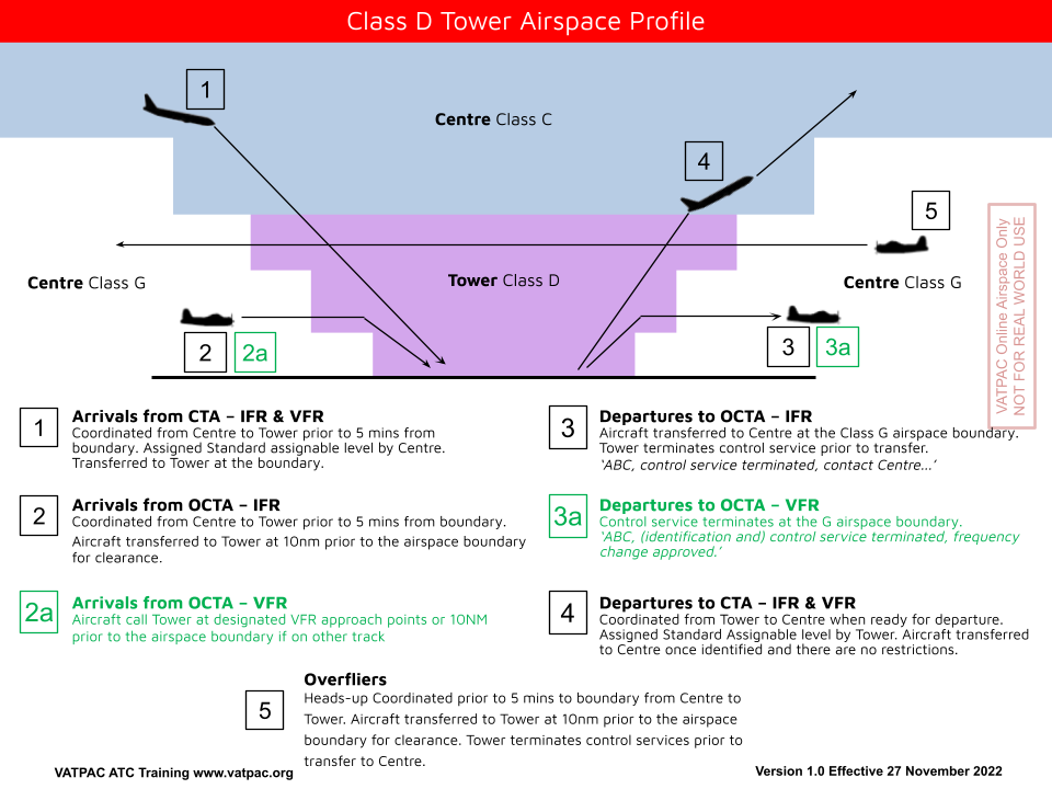
Remember that in Class D Airspace, IFR aircraft are separated from IFR and SVFR, and SVFR is separated from SVFR when visibility is not VMC. No separation is provided for VFR aircraft, even though it is controlled airspace. The Tower Controller provides more of a "segregation" service (ie, providing reasonable opportunity for the aircraft to separate themselves), as well as providing traffic information.
Surveillance
Although surveillance standards cannot be used for separation at Class D Towers, overlying TCU/Enroute controllers can use their surveillance standards to help Class D towers achieve separation, when procedural separation is a bit awkward or impractical.
Phraseology
AY ADC -> BLA: "Can you advise when QLK208D is 5nm clear of DSB?"
BLA -> AY ADC: "Affirm, will do"
...
BLA -> AY ADC: "QLK208D, 5nm clear of DSB"
AY ADC -> BLA: "QLK208D, 5nm clear of DSB, thanks"
Lateral
Lat Sep Table
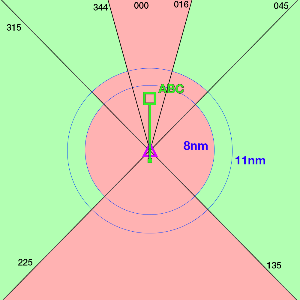
When two aircraft are on intersecting tracks, lateral separation is established based on the interception angle and distance between the aircraft.
The calculation of the lateral separation point is tabulated below:
| Tracks intersecting at | Lat Sep point |
|---|---|
| 0°-15° | No lateral separation |
| 16°-44° | 11nm |
| 44°-135° | 8nm |
| 136°-180° | No lateral separation |
In a more visual form, ABC can be considered to be laterally separated from aircraft in the green areas, and not laterally separated from aircraft in the red areas. This only applies to intersecting angles at the crossing point, and both aircraft tracking directly to/from the crossing point.
Conflict Area
Two aircraft are considered to be in lateral conflict when they are within the relevant Circular Error of Position (CEP) distance of each other. The Conflict Area tool can help identify the region in which the aircraft lose lateral separation assurance along their cleared routes.
The CEP is dependent on an aircraft's navigation capability, which is described in their flight plan remarks by the NAV/xxx descriptor.
NAVCAPs
All aircraft have a NAVCAP, associated with a Circular Error of Position. This helps determine which number to select when using the Conflict Area Tool:
| NAVCAP Code | Meaning | Circular Error of Position (CEP) |
|---|---|---|
| A | All | 7nm |
| 2 | RNP2 | 7nm |
| 4 | RNP4 | 14nm |
| 5 | RNAV5 | 14nm |
| T | RNAV10 | 14nm |
| Z | None | 30nm |
The minimum number you must select when using the tool, is equal to: Aircraft 1 CEP + Aircraft 2 CEP + 1nm
Example
Aircraft 1 NAVCAP: 4
Aircraft 2 NAVCAP: Z
14+30+1=45
Example
Aircraft 1 NAVCAP: 2
Aircraft 2 NAVCAP: A
7+7+1=15
Tip
The best scenario is to have 2 aircraft that are RNP2 approved. "Feed the beast" in order to get what you want, that is to say "QFA12, confirm you are RNP2 approved?", and they'll probably say yes. Enter NAV/RNP2 in the flight plan remarks, and you can use a 7nm CEP.
Separation
With each CEP calculated and the conflict area determined, controllers must ensure another separation standard is in place before the aircraft enter the conflict area.
Definite Passing
Aircraft on reciprocal tracks (or converging/diverging tracks at least 90° apart) are laterally separated when there is at least 10nm between them. The distance may be measured with reference to a DME or waypoint.
Geographic Features
Two aircraft are considered to be laterally separated where both are operating with visual reference to a fixed geographic feature, such as a coastline, river, large highway, etc.
A 1nm buffer must be applied to one aircraft's tracking.

Example
Aircraft A operating 1nm East of the Pacific Highway
is laterally separated from
Aircraft B operating West of the Pacific Highway.
Aircraft C operating North of the Murray River
is not laterally separated from
Aircraft D operating South of the Murray River.
Phraseology
RXA6418 is inbound to YCFS from the south and has reported visual. They are vertically separated from an outbound aircraft who is departing to the south.
CFS ADC: "RXA6418, track to remain 1nm offshore, report established"
RXA6418: "Track to remain 1nm offshore, RXA6418"
RXA6418: "RXA6418, established 1nm offshore"
RXA6418 is now separated from aircraft operating over land, allowing ADC to issue further descent.
CFS ADC: "RXA6418, descend to A050"
RXA6418: "Descend A050, RXA6418"
Once both aircraft have passed and/or another separation standard is available (e.g. vertical separation), the geographic feature standard can be relaxed.
CFS ADC: "RXA6418, cancel the offshore requirement, track for downwind runway 21, cleared visual approach"
Departures
2 min
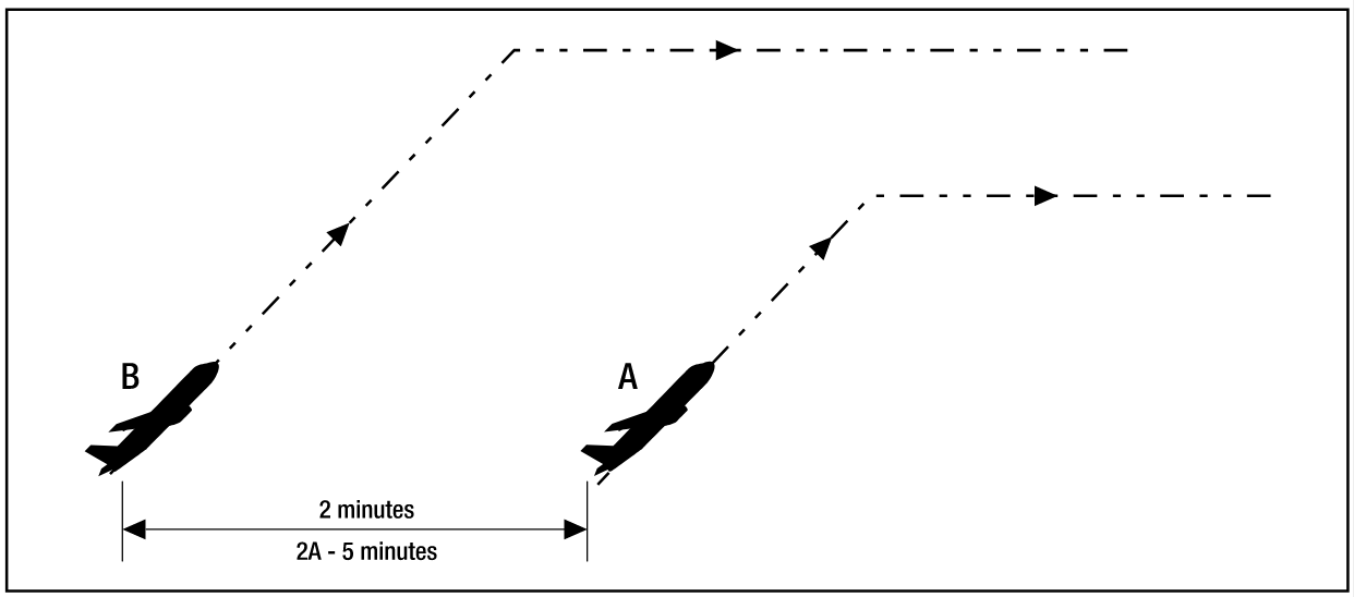
Two departing aircraft may be departed with 2 min spacing and be considered separated provided the conditions below are met.
| Conditions | |
|---|---|
| a) The aircraft are climbing to vertically separated levels; b) Both aircraft report reaching the cruising level; c) If the following aircraft is climbing to a lower level than the preceding aircraft, and reaches that level first, apply another form of separation immediately; and d) climb and cruising IAS of the following aircraft is at least 10 kt slower and not more than 90% of the climb and cruising IAS or Mach number of the leading aircraft. |
|
 |
|
5 min
Two departing aircraft may be departed with 5 min spacing and be considered separated provided the conditions below are met.
| Conditions | |
|---|---|
| a) Both aircraft report reaching the cruising level; b) If the following aircraft reaches that level first, apply another form of separation immediately; and c) climb and cruising IAS of the following aircraft is at least 10 kt slower and not more than 90% of the climb and cruising IAS or Mach number of the leading aircraft. |
|
 |
|
10 min
Two departing aircraft may be departed with 10 min spacing and be considered separated provided the conditions below are met.
| Conditions | |
|---|---|
| a) Both aircraft report reaching the cruising level; b) If the following aircraft reaches cruising level first, apply another form of separation immediately; and c) climb IAS of the following aircraft is less than or equal to the climb IAS of the leading aircraft. |
|
 |
|
Arrivals
10nm
Two arriving aircraft may be processed with 10nm spacing and be considered separated provided the conditions below are met.
| Conditions | |
|---|---|
| a) Both aircraft are inbound, and the leading aircraft is within 20nm of a controlled aerodrome; and b) The aircraft are assigned vertically separated levels. |
|
 |
|
Visually Acquired Aircraft
Two aircraft may be considered to be separated if the second aircraft is beyond the view of the controller (i.e. greater than 10nm from the aerodrome), provided:
- the first aircraft has been sighted by the tower controller within 10nm, and
- a landing/missed approach can be effected clear of conflict
In practice, this allows controllers to reduce the spacing between successive arrivals via an instrument approach provided the weather conditions will allow the controller to visually acquire each aircraft within 10nm of the aerodrome and before the following aircraft commences the approach.
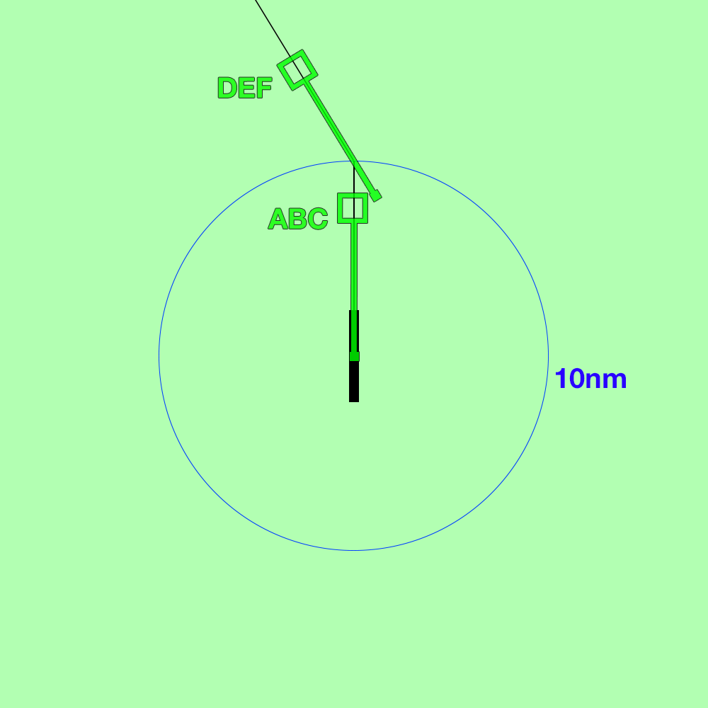
45° Segregated Flight Paths
Straight-in
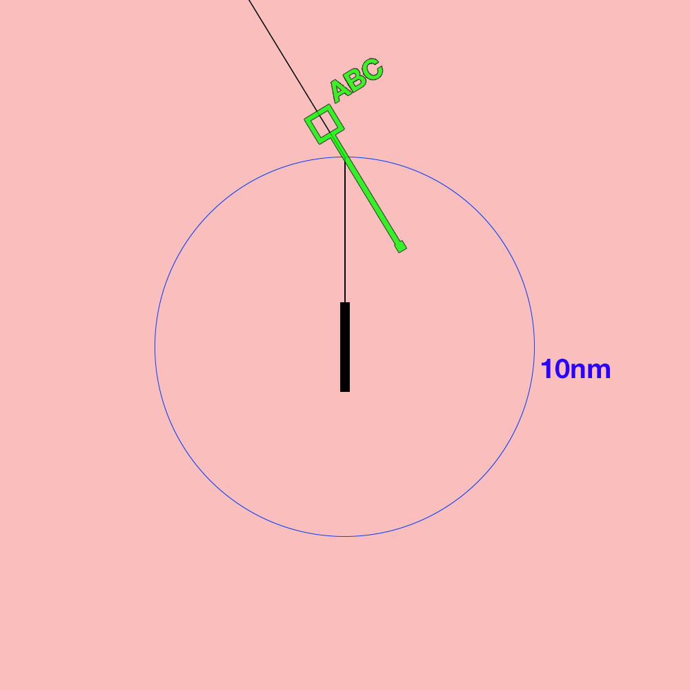
- Can be applied between departures and arrivals when the departing aircraft's flight path and the arrival aircraft's flight path are at least 45° clear of each other, and, for a straight-in approach, the arriving aircraft is at least 5nm from the arrival runway threshold


Visual, DME/GNSS, Circle to land
- Can be applied between departures and arrivals when the departing aircraft's flight path and the arrival aircraft's flight path are at least 45° clear of each other, and, for a Visual, DME/GNSS or Circle to land approach, the arriving aircraft is at least 10nm from the airfield


Vertical
1000ft between all applicable aircraft.
See Also
Any non-surveillance separation standard can also be used, however these are generally impractical in the small volume of airspace operated by a procedural tower. However, the following pages may prove useful: