Tower Strips
In the real world, aerodrome controllers use strips to provide a visual representation of aerodrome activity, beyond what looking out the window or at a radar screen can provide.
Within vatSys, this can be emulated using the OzStrips plugin. Strip state is shared between controllers operating at the same aerodrome.
Setup
Installation
The plugin is included by default in the Australia and Pacific vatSys profiles provided by VATPAC. No installation action is required from controllers.
Important
Controllers should not install the plugin manually when using the Australia or Pacific vatSys profiles, as doing so can create unstable plugin behaviour.
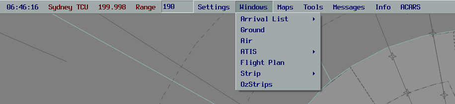
If the client is installed correctly, there will be an OzStrips option in the Window dropdown menu.
Connecting
OzStrips automatically manages the list of aerodromes available, depending on the position and sectors you have set. The desired aerodrome can be chosen from this list.
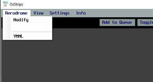
A connection attempt will be made and if successful, the CONN STAT field in the Control Bar will turn green.
Tip
Pressing [ and ] will cycle through the aerodromes in the dropdown menu, allowing controllers to provide top down coverage to multiple locations easily.
Configuring Views
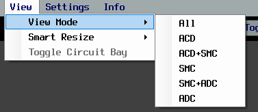
Once connected to the relevant aerodrome, controllers should select the view mode which is most suitable for their position. Use the View Mode menu item to select a layout.
The size of each strip can be adjusted using the Strip Scale slider, under Help > Settings. Users with limited screen real estate may benefit from using a smaller strip size.
The plugin window will adjust to being resized, automatically collapsing into a two and single column layout, which is helpful for users with small screens.
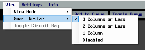
By default, the height of each strip bay is fixed, however using the Smart Resize functionality, they can be set to a dynamic height based on the number of strips in each bay. This is helpful when using the plugin in a collapsed column layout or with limited screen height.
Stripboard
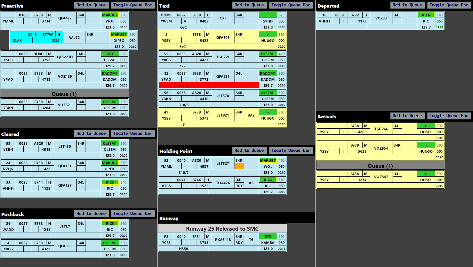
The stripboard is divided into multiple bays, each representing a stage in an aircraft's flight thread.
Strips can be moved in between strip bays by clicking on their callsign, and clicking the bay where you want them to go. Strips can be moved to the next bay by clicking on the SID box (referred to as SID triggering).
Various layouts exist to handle radar towers, procedural Class D towers, and Metro D towers.
Missing Strips
Selecting a track on the Ground Radar or ASD will select the relevant strip in OzStrips, and vice versa. If a strip is missing from the stripboard, select the ground track from the vatSys Ground window, then click the desired OzStrips bay to place the strip there.
Alternatively, the Quick Search window can be opened by pressing CTRL + F, allowing controllers to enter a callsign and see which bay the strip resides in.
Control Bar
The bottom of the window holds the Control Bar. This panel contains the server connection status, aerodrome selected and ATIS code, among other elements.
Each button has the following function:
| Button | Function |
|---|---|
| INHIBIT | Hides a strip from the stripboard (used when a strip is no longer needed) |
| XX CROSS XX | Opens the Runway Cross window, allowing controllers to toggle the state of a particular runway |
| XX RELEASE XX | Opens the Runway Release window, allowing controllers to toggle the state of a particular runway |
| ADD BAR | Allows controllers to place a variety of fixed bars anywhere on the stripboard, reflecting status changes (e.g. autorelease cancellation) and allowing bays to be separated (e.g. multiple SMC/ADC positions open) |
| FLIP | Toggles the selected strip between Departure, Arrival & Local states (for aircraft with both ADES and ADEP fields matching the current aerodrome) |
Strips
The background colour of the strip corresponds to its status as an arrival or a departure. Departing aircraft have a blue strip, arriving aircraft have a yellow strip, and local aircraft have a pink strip.

| Number | Content | Left Click | Right Click | Middle Click |
|---|---|---|---|---|
| 1 | Bay Number | Edit Bay Number | ||
| 2 | CDM or Off Blocks Time No Background = Filed Off Blocks Time Coloured Background = CDM Time |
Cock Strip | Open CDM Information Window | |
| 3 | Aircraft Type | Open Flightplan | ||
| 4 | Wake Turbulence Category | |||
| 5 | Destination | Open Flightplan | ||
| 6 | Voice Capability Indicator Empty = Voice Capable R = Receive Only T = Text Only |
Show Route | ||
| 7 | Flight Rules | Show Route | ||
| 8 | PDC Sent Indicator Empty = PDC not sent Highlighted = PDC Requested P = PDC sent |
Open PDC Window | Open Private Message | |
| 9 | SSR Code | Autogenerate Code | ||
| 10 | Callsign | Select Strip | ||
| 11 | Runway | Change Runway | ||
| 12 | Ready Flag | Toggle Ready Flag | ||
| 13 | Holding Point | Edit Holding Point | ||
| 14 | SID | Move strip to next bay | Change SID | Inhibit VFR Assigned SID Warning |
| 15 | First Waypoint | Open flightplan | Open Reroute Window | Inhibit Route Warning |
| 16 | Requested Level | Open flightplan | Inhibit RFL Warning | |
| 17 | Cleared Level | Change CFL | ||
| 18 | vatSys Global Ops Field | Edit | ||
| 19 | OzStrips Remarks | Edit | ||
| 20 | Departure Frequency | Open Departure Frequency Window | ||
| 21 | Takeoff Timer | Start / Reset |

Local Flights
Aircraft intending to conduct operations entirely on the ADC frequency (most commonly circuits or helicopter operations in ADC jurisdiction) should be marked as a local strip.
Select the strip, then use the Flip button to 'flip' the strip into a pink, local strip.
Aircraft who have filed flightplans which depart from and arrive back to the same aerodrome can be toggled between Departure and Arrival states using the Flip button.
Note
Only aircraft who will remain on the ADC frequency should be marked as local strips. If an aircraft will depart the aerodrome and conduct operations elsewhere, then return for landing, they should be treated as a departure. These strips should then be flipped to Arrival state when they return.
Keyboard Shortcuts
The following keyboard shortcuts exist to improve workflow efficiency.
| Shortcut | Function |
|---|---|
Enter |
SID trigger selected strip to next bay |
Tab |
Cock/uncock selected strip |
Space |
Queue/unqueue selected strip |
Backspace |
Inhibit selected strip |
F |
Flip (cycle between Departure, Arrival & Local states) selected strip |
T |
Select the strip of the last aircraft to transmit on frequency |
W |
Highlight the strip of the last aircraft to transmit on frequency |
X |
Toggle crossing highlight to selected strip |
Alt + R |
Toggle Runway Release window |
Alt + X |
Toggle Runway Crossing window |
[ / ] |
Change aerodrome |
↑ / ↓ |
Move selected strip position in the current bay |
Ctrl + ↑ / Ctrl + ↓ |
Move selected strip towards nearest bar |
Ctrl + F |
Open Quick Search window |
Tip
These keybinds can be adjusted through Settings.
Workflow
Due to it's shared state, OzStrips works best if all controllers follow a standardised workflow. Controllers are strongly encouraged to follow the workflow below.
Delivery
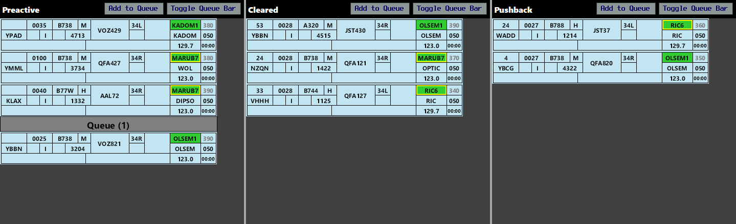
Fill out the strip of recently connected aircraft so that you can identify any problems with their filed flight plan before they request clearance. Aircraft wishing to conduct circuits or other operations remaining entirely on the ADC frequency, should be marked as local strips.
Tip
With a strip selected, press F to flip it between Departure, Arrival, and Local states.
Flight Plan Errors
OzStrips will flag any potentially invalid routes and incorrect hemispherical levels. Hover over a flag to learn more about the error.


Right mouse click on the yellow First Waypoint box to open the Reroute menu. From here, controllers can select a more compliant route. The VATPAC Tools page can be helpful to double check these routes.
Important
The invalid route detection system compares the filed route against any ERSA FPR requirements. Some valid routes may flag where the route deviates from FPR guidance. Some invalid routes may not flag where no FPR guidance exists for that aerodrome pairing.
ACD controllers must ensure they continue to check each route for errors regardless of strip error status.

Some situations may warrant acknowledging and removing an error/caution mentioned above (e.g. VFR aircraft conducting a SID for training, a filed route not matching an ERSA FPR entry but which is not otherwise invalid, etc.). In these cases, they can be removed by middle clicking on the relevant field.
Autofill
OzStrips includes an autofill system to automatically set the departure runway, SID, CFL, and departure frequency. Autofill is only available when a valid ATIS is published for the aerodrome and the necessary config file exists.
Tip
The autofill status is shown in the menu bar.
To use autofill, select a strip, then press A.
To issue a non-standard runway, SID, or other element, first enter the desired data, then press A to autofill the remaining elements.
Important
It is the responsibility of ACD to verify the accuracy of any data entered by the autofill system. Invalid or incomplete ATISes may cause errors in the outputted data.
Issuing Clearance
When an aircraft requests airways clearance, select the strip to avoid losing it from view, then deliver the clearance. Upon receiving a correct readback, enter the aircraft's parking bay in the Bay field, then move it to the Cleared Bay.
If multiple aircraft request clearance at once, queue the strips for each aircraft, in the order in which they called.
SIDs with a transition are indicated by a yellow border on the SID box. Hover over the box to reveal the transition.

For flight plans with a GPS waypoint as the first tracking point, the First Waypoint box will show #GPS#.
For flight plans with a custom waypoint derived from position bearing distance (e.g. WLM045008), the First Waypoint box will show the waypoint followed by a plus (e.g. WLM +).
In both cases, ACD must open the FDR to read the first waypoint.
PDCs
At YMML, YSSY, YPAD, YPPH, YBBN, YSCB, YPDN, YBCG, YBCS, YBTL, and YWLM, PDCs may be sent via the Hoppies network to integrate directly with aircraft avionics. At all other aerodromes, and for any aircraft not able to receive a Hoppies PDC, PDCs will be sent via private message. OzStrips will handle the Hoppies connection automatically, there is no configuration required by the controller.
When a pilot requests a PDC via Hoppies, the PDC Indicator will flash yellow/white until acknowledged and the Requested PDCs element in the menu bar will highlight.
To issue a PDC, fill out all required fields in the strip, then click the PDC Indicator to open the PDC window. Verify the message, then click Send.
Tip
OzStrips will send the PDC via the most appropriate method (either Hoppies or private message) automatically. No action is required from the controller to determine or set the transmission method.
Departure Frequency
The issued departure frequency should be recorded in the Departure Frequency field. Clicking on the element will open a window containing all relevant frequencies currently primed by a TMA or ENR controller. If there are no relevant controllers online, the advisory frequency will be the only selectable option.
Note
As various controllers connect and disconnect, ACD, SMC, or ADC will need to update the departure frequency for each aircraft. The departure frequency field should only be changed when the pilot is informed of the new frequency, to allow controllers to determine which aircraft have been issued the frequency change.
Pushback Requests on ACD
When pushback requests are being managed by ACD, the procedures set out in Coordinator below shall be followed.
Tip
Whilst not a requirement, controllers may find it beneficial to utilise CDM Mode to manage the pushback rate where congestion is likely at the holding point.
Coordinator
At locations like Brisbane, Melbourne, Perth, Sydney, and Walton, a Coordinator role is sometimes performed during times of high traffic. See each aerodrome-specific page for the requirements to open and set up the Coordinator position.
Note
At most aerodromes, this duty is performed by ACD (when required), but for simplicity, this section will refer to the controller performing the role as 'Coordinator'.
Once all coordination has been completed and the Coordinator position has been opened, all outbound aircraft must first request pushback or taxi on the Coordinator frequency before being passed to SMC.
Enable the Monitor SMC Bay by selecting View > Toggle Monitor SMC Bay. Any strips in this bay respresent aircraft who have been instructed to standby for ground on the appropriate SMC frequency. Aircraft who are ready for pushback or taxi, but have not been told to monitor SMC, are queued in the Cleared Bay.
As a general rule, ensure that no more than three strips are present in the Monitor SMC Bay. When SMC takes a strip from the bay and places it in the Pushback or Taxi Bay, instruct the aircraft next in line to monitor SMC, and move them to the bay.
See Pushback Requests on ACD for detailed Coordinator decision-making procedures.
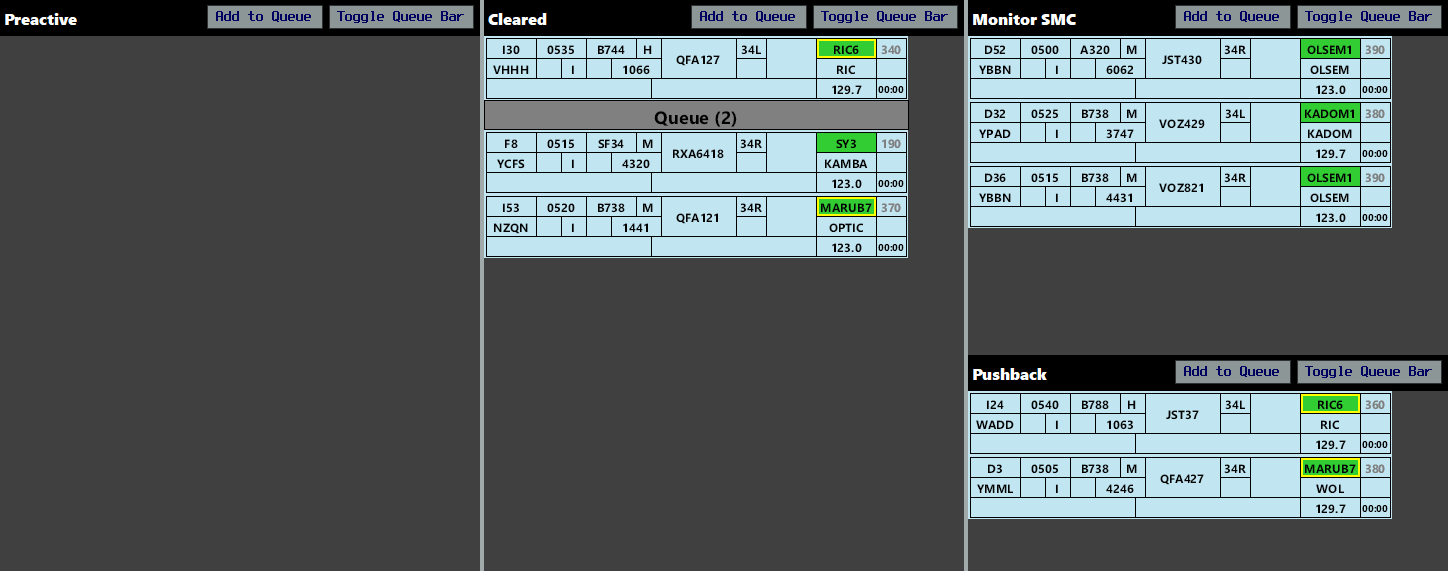
Three aircraft are waiting on the SMC frequency (in the Monitor SMC Bay), and QFA121 and RXA6418 have both requested push/taxi but are being held on the Coordinator frequency. QFA121 is closer to the bottom, so will be next to be told to standby for SMC.
Ground
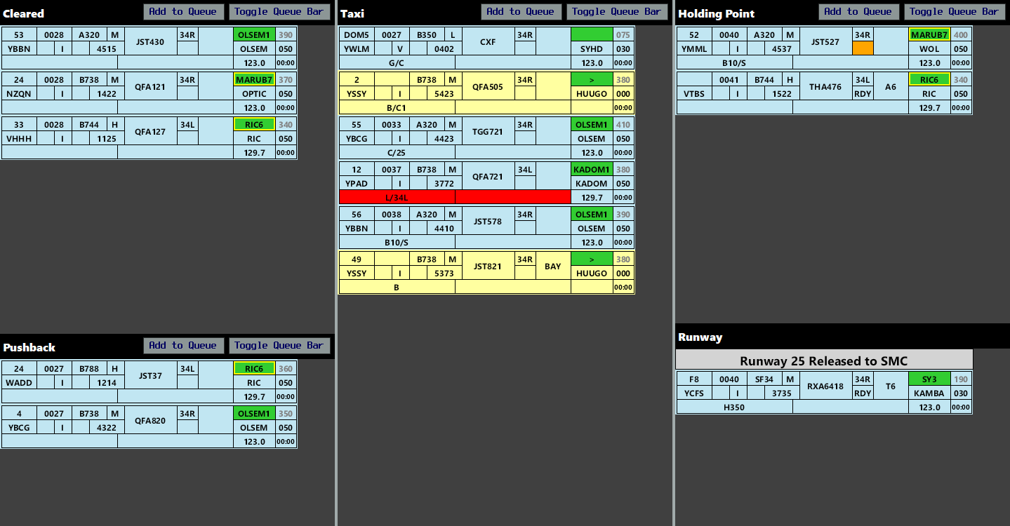
Departures
When a departure is issued pushback, move them to the Pushback Bay. If pushback is unable to be given at that time, queue the strip in the Cleared Bay.
Tip
See Coordinator above for the procedure to follow when a Coordinator position is active (or pushback requests are being managed by ACD). Remember that the bottom most aircraft is always the first in line.
Note
When CDM Mode is enabled, pushback should only be issued when the Offblocks field is green. Pushback should be withheld if necessary due to aerodrome congestion (OzStrips will adjust queued aircraft's TSATs accordingly).
When taxi instructions are issued, move the strip to the Taxi Bay and enter the relevant instructions in the Global Ops field. When the aircraft is given taxi to the holding point at their assigned departure runway, enter the holding point in the Holding Point field.
OzStrips will check the output of a departure's transponder to ensure they are squawking the assigned SSR code and have selected Mode C. If either of these two conditions are not met, the squawk box will highlight orange.

As the aircraft approaches the holding point, or when frequency transfer is given to Tower (for international aircraft or new pilots), move the strip to the Holding Point Bay and clear the Global Ops field (so ADC can use it for their purposes).
Arrivals
As an arriving aircraft vacates the runway, ADC will move the strip from the Runway Bay to the Taxi Bay. Enter the pilot's nominated parking bay in the Bay field and record any taxi instructions in the Global Ops field.
When an aircraft is cleared to the bay, put BAY in the Holding Point box.
When an aircraft arrives at their nominated parking position, inhibit the strip to remove it from the stripboard.
OzBays Integration
At OzBays-enabled aerodromes, the pre-assigned parking bay from OzBays will be displayed automatically in the parking bay field for arriving aircraft.
Pre-assigned OzBays bays are displayed with a grey background. These bays can be overridden by editing the field manually. To display the pre-assigned bay again, edit the field and clear out your input.
Note
OzBays is currently in final development and testing, and will be progressively enabled for each aerodrome.
Runway Crossings
For aircraft who need to cross an active runway, select the strip and apply the crossing highlight. SMC should hotline ADC to request each runway crossing and/or place the strip in the Holding Point Bay with the crossing highlight applied, as a visual trigger to ADC that an aircraft needs to cross. Once ADC has approved the runway crossing, place the strip back in the Taxi Bay and remove the highlight.
Tip
You can quickly toggle the crossing highlight by selecting an aircraft and pressing X.
There is no need to highlight a taxiing aircraft crossing a runway which has been released to SMC.

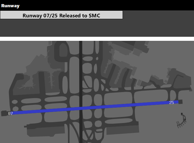
Coordinated runway releases should be recorded by clicking the XX RELEASE XX button and selecting the applicable runway. This will highlight the runway in blue to visualise the release.
Tower
Departures
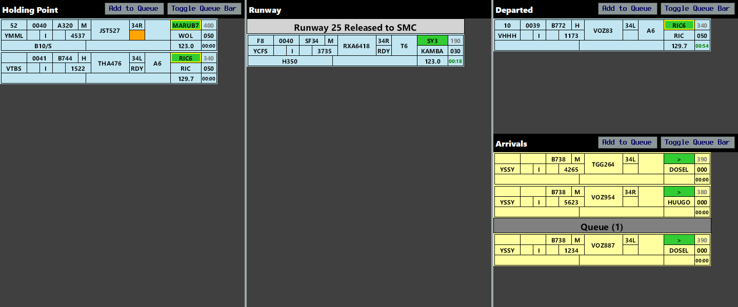
When a departing aircraft calls ready, click the Ready flag to denote this on their strip. You can adjust the order of the departure sequence by selecting each strip and using the arrow keys to move them up and down. Strips at the bottom of the bay are first in line.
Tip
The Ready flag will highlight orange if the aircraft is in the Holding Point Bay and the aircraft has not called ready (to prevent inadvertent takeoff clearances being issued).
For aircraft on a radar SID or visual departure, record any assigned heading instructions in the Global Ops field. The Global Ops field will highlight orange for aircraft assigned a radar SID who have not yet had their departure instructions entered.

When an instruction to line up is given, move the strip to the Runway Bay. When a takeoff clearance is issued, start the Takeoff Timer.
When the aircraft has been transferred to the Departures controller, move the strip to the Departed Bay.
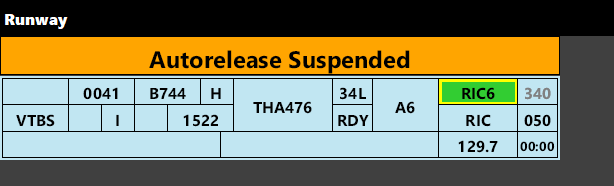
If the TCU suspends autorelease, record this by placing the AUTORELEASE SUSPENDED bar in the Runway Bay.
Tip
During busy 'conga line' events, like Milk Run Monday, controllers may find it beneficial to utilise CDM Mode to manage the departure rate and avoid overwhelming the TCU and downstream enroute controllers.
This mode is only beneficial to ADC where the departure rate is important and will be less beneficial for events where aircraft depart in a wide variety of outbound directions.
Arrivals
Order the Arrivals Bay so that the next aircraft to land are positioned at the bottom. When an aircraft calls you on Tower frequency, queue them. When a landing clearance is issued, move the strip to the Runway Bay.
After the aircraft vacates the runway, move the strip to the Taxi Bay.
Tip
By default, the Taxi Bay is not visible in the ADC layout. To move a strip from the Runway Bay to the Taxi Bay, SID trigger the strip (or use the appropriate keyboard shortcut). This works for arrivals only, and departing strips SID trigger to the Departed Bay.
Circuits
Pink local strips denote aircraft who's planned operation remains entirely on the ADC frequency (they will not be passed to Departures or leave ADC's jurisdiction). Normal departure procedures apply for recording when the circuit aircraft calls ready and is eventually cleared for takeoff.
The Circuit Bay can be toggled on and off using the option within the View dropdown.
Once the aircraft is airborne, move the strip to the Circuit Bay and sequence them with any other arriving aircraft. On each circuit, move the strip to the Runway Bay when a landing/touch & go/other clearance is issued, then move them back to the Circuit Bay when they become airborne again.
When the aircraft lands for the final time and vacates the runway, use the Flip button to change their state to Arrival and place them in the Taxi Bay in accordance with normal arrival procedures.
Tip
With a strip selected, press F to flip it between Departure, Arrival, and Local states.
Coordinated circuit area airspace releases should be recorded by placing a CIRCUIT AREA RELEASED bar in the Circuit Bay.
Runway Crossings
Aircraft who need to cross an active runway will be coordinated by SMC by hotline and/or by SMC placing the strip in the Holding Point Bay with the red crossing highlight applied.
Where workload permits, ADC may proactively coordinate with SMC to approve runway crossings based the presence of a strip in the Holding Point Bay.
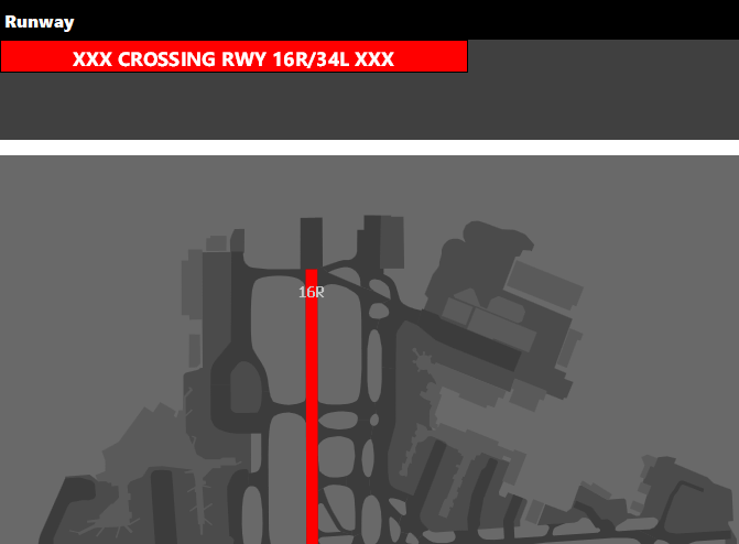
Approved runway crossings should be recorded by clicking the XX CROSS XX button and selecting the applicable runway. This will highlight the runway in red, preventing inadvertent takeoff or landing clearances from being issued. Once the aircraft is clear, remove the Crossing bar from the Runway Bay.
Tip
You can quickly toggle a runway crossing by pressing ALT + X.
Coordinated runway releases should be recorded by clicking the XX RELEASE XX button and selecting the applicable runway. This will highlight the runway in blue to visualise the release.
Tip
You can quickly toggle a runway release by pressing ALT + R.
Class D Tower
Procedural Class D Tower layouts feature an Active Bay, designed to hold all aircraft under jurisdiction of ADC, active in their airspace.
When an aircraft becomes airborne or is handed off to ADC, place the strip at the bottom of the Active Bay. Compare the strip with the strip immediately above it and consider any potential conflict. If no conflict exists, that strip may be moved up a position in the bay and the process repeated with the next 'blocking' strip above. Once the strip reaches the top of the bay, no further conflict exists and the aircraft can be handed off to the overlying controller or cleared for an approach (as appropriate).
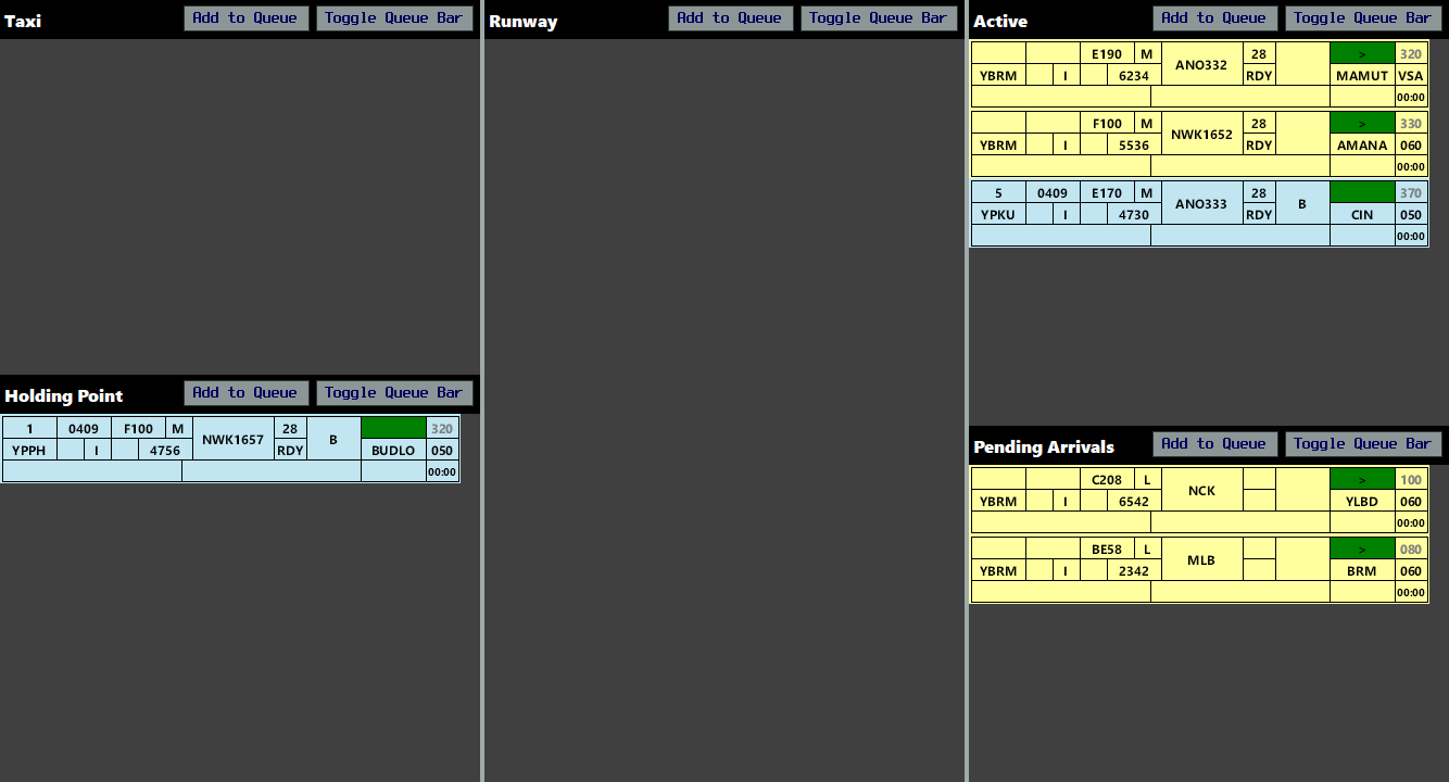
ANO333 is 'blocked' by NWK1652 and will not receive further climb until the two aircraft have adequate separation
Note
Metro D positions feature a similar layout with the Circuit Bay displayed by default and no Active Bay (due to their lack of airspace).
Multiple ADC/SMC Positions
When multiple ADC or SMC positions are online at a given aerodrome, place divider bars in the relevant bays, allowing each controller to process only the aircraft relevant to them.
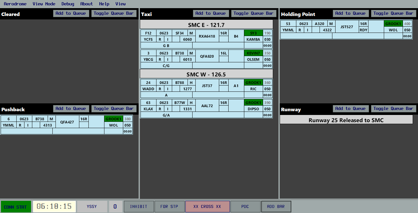
Tip
With a strip selected, use CTRL + UP/DOWN ARROW to push that strip up or down to the next bar (or queue bar).
Workload Management
Several features of OzStrips allow controllers to effectively manage their workload. Ensure that every instruction which is issued over the radio is also recorded in the aircraft's strip.
Important
Ensure that you communicate instructions concurrently while you move strips in OzStrips. Don't move strips before you do the action or obtain a readback, incase you get interrupted.
Cocking Strips
Left clicking on the strip's EOBT will highlight and cock the strip, making it stand out. It is recommended to mark strips this way if there is an outstanding request.
Tip
With a strip selected, pressing TAB will cock or uncock it.
Queue Management
When multiple aircraft have outstanding requests, it is recommended you 'queue up' the strip, by placing them below the queue bar. This can be done quickly by selecting the strip then pressing "Add to Queue".
Tip
With a strip selected, pressing SPACEBAR will queue or unqueue it.
Strips can be moved vertically by pressing the keyboard arrow keys while a strip is selected. Aircraft at the bottom of the queue are first in line.
When an aircraft is in a queue, make sure the strip's bay location represents its current state.
Example
An aircraft in a queue for an airways clearance, would remain in the Preactive Bay, below the queue bar, not in the Cleared Bay.
Runway Crossings
As per Runway Crossings, the red crossing highlight should be applied to any aircraft who need to cross an active runway. SMC should consider doing this in conjunction with issuing the initial taxi instructions, as a visual reminder of the coordination which will be required. SMC should hotline ADC for each crossing and/or place the highlighted strip in the Holding Point Bay, as a prompt to ADC that a crossing is required.
ADC should monitor the Holding Point Bay and proactively hotline SMC where a suitable gap exists to facilitate the runway crossing. Alternatively, SMC should hotline ADC to request the crossing when required. Planning runway crossings in advance, including crossing multiple aircraft at different taxiways at the same time, can drastically improve overall runway efficiency.
Tip
On long runways with readily available rapid exit taxiways (e.g. RWY 34L at YSSY), ADC may instruct landing aircraft to 'report taxiway B9 assured' and upon receiving this confirmation, hotline SMC to approve the crossing of an aircraft further upwind of the runway exit.
A-CDM
During events, or when traffic flow management procedures are warranted, CDM mode can be enabled for the aerodrome. A CDM Processor at each aerodrome keeps track of which stage of departure each aircraft is in. Active and Pushed aircraft are included within the Departure Queue, and will have a TSAT and CTOT time calculated for each aircraft.
Note
The departure queue (as well as a range of statistics) is available on the Ops Dashboard.
Departure Rates
The target departure rate can be adjusted on the Ops Dashboard. Log in to the site to make adjustments.
The default rate is 30 per hour. This works well for most aerodromes where traffic is both inbound and outbound (allowing sufficient time for an arrival to land between departures). The rate should be adjusted as required based on:
- holding point congestion
- busy arrival sequence
- at the request of an upline controller
Note
Airports with multiple departure runways should increase the departure rate to compensate for the added runway capacity.
Specific rates can be set for departures to particular aerodromes. This is particularly useful for events where the destination aerodrome may be rate-limited.
Example
During Milk Run Monday, Sydney ACD sets a departure rate of 40 per hour and a YMML-specific rate of 24 per hour.
CDM Stages
| Name | OzStrips Bay | CDM Processor Action |
|---|---|---|
| Preactive | Preactive or Cleared Bay above the bar | Not included in CDM calculations |
| Active | Cleared Bay, below the queue bar | Included within the departure queue, and will be issued a TSAT and CTOT |
| Pushed | Pushback, Taxi, Holding Point or Runway Bay | Included in the departure queue below any Active aircraft |
| Complete | Departed Bay, or GS > 50kts | Departure time is logged, not included in CDM calculations |
If an aircraft disconnects, or their strip is moved into the Preactive Bay or Cleared Bay above the bar, their CDM status will expire after 3 minutes.


CDM Abbreviations
| Abbreviation | Full Name | Explanation | Example |
|---|---|---|---|
| EOBT | Estimated Off Blocks Time | The off blocks time a pilot submits within their flight plan. This is not used for CDM calculations. | 10:00z |
| TOBT | Tactical Off Blocks Time | The time at which the pilot requests pushback. | 10:20z |
| TSAT | Tactical Start Approved Time | The time the CDM processor allots for pushback approval, taking into account CDM parameters and other aircraft. | 10:30z |
| AOBT | Actual Off Blocks Time | The time at which the aircraft actually pushes back. This should be as close to the final TSAT as possible | 10:31z |
| CTOT | Calculated Take Off TIme | The time the CDM system allots for aircraft departure. | 10:45z |
| ATOT | Actual Take Off Time | The time at which the aircraft actually departs. | 10:46z |
Pushback Process
Pushback should only be issued when the aircraft is compliant with their TSAT.
| Colour | Condition | Explanation |
|---|---|---|
| Grey | In Queue | The aircraft has been placed in the queue but is not yet compliant with their TSAT. Do not issue pushback. |
| Green | Compliant with TSAT | The aircraft is compliant with their TSAT. Pushback may be issued if aerodrome congestion allows. |
| Yellow | Pushed Back | Aircraft has already pushed back, no further action required. |
Controllers should follow the procedures detailed on the Ground Delay Management page.
CDM Processing
CDM Processing refers to the process by which the departure order, TSAT and CTOT times are calculated for each aircraft. This occurs regularly at CDM enabled aerodromes, and after every CDM-relevant aircraft state change.
The CDM Processor takes the list of active and pushed aircraft, as well as the set Departure Rate, determines a priority sorted list of aircraft, and allocates a CTOT to each aircraft. CTOT times will be spaced by the set Departure Rate. A TSAT is calculated for each aircraft, based on the CTOT. TSAT times take into account the aircraft state, such that an aircraft will not be expected to pushback and depart within 5 minutes. CTOT and TSAT times are recalculated during each CDM Processing cycle, and can vary from the initial TSAT issued.
Example
A planned Departure Rate of 30/hour is set, but the ADC controller actually maintains a rate of 40/hour. AOBT and ATOT will be earlier than the initial calculated TSAT and CTOT.
Departure Monitoring
The Departure Rate is set based on conditions at the aerodrome, the amount of departures, the amount of arrivals, and amount of arrivals the destination aerodromes can accept. For the A-CDM system to work effectively, ADC must monitor the amount of depatures they release, and ensure this actual rate is as close to the set departure rate as possible.
To make this task easier, OzStrips provides a Departure Monitor screen above the Runway Bay when CDM is enabled at an aerodrome. The Departure Rate over the preceeding 5, 15 and 30 minutes are recorded, and presented to plugin users. Each interval is colour coded to quickly show the relative performance vs planned performance.
| Colour | Conditions | Explanation |
|---|---|---|
| Purple | Way Below Target (-3 or less) | Departure capacity is very underutilised |
| Blue | Slightly Below Target (-1 to -2) | Departure capacity is slightly underutilised |
| Green | On Target (+/- 0) | The set departure rate is being perfectly executed |
| Orange | Above Target (+1 to +2) | Slightly too many departures have been released |
| Red | Way Above Target (+3 or more) | Too many departures have been released |

The ADC controller(s) should aim to ensure the amount of aircraft they release matches these values as close as possible. While over-exceeding departure capacity is easily preventable, sometimes departure capacity can be underutilised due to ground-stops or not enough aircraft demand.