Cairns (YBCS)
Positions
| Name | Callsign | Frequency | Login ID |
|---|---|---|---|
| Cairns ADC | Cairns Tower | 124.900 | CS_TWR |
| Cairns SMC | Cairns Ground | 121.700 | CS_GND |
| Cairns ACD | Cairns Delivery | 128.750 | CS_DEL |
| Cairns ATIS | 131.100 | YBCS_ATIS |
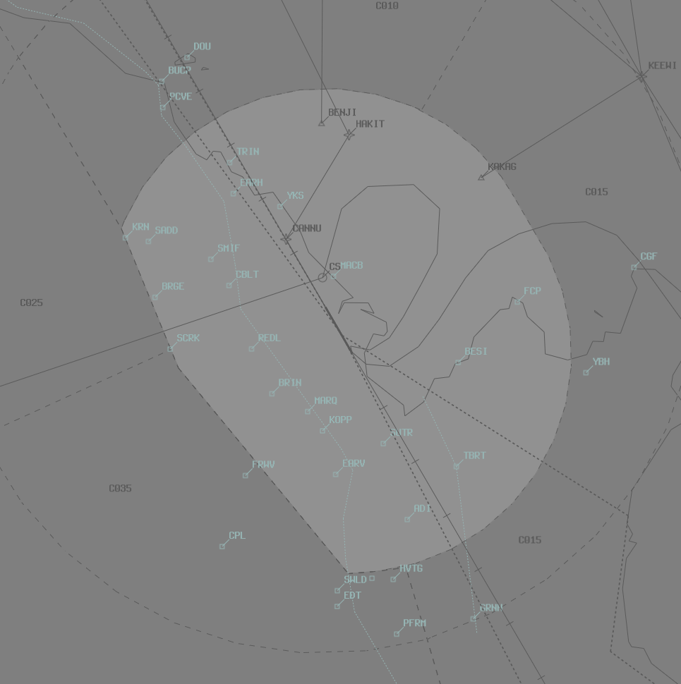
Airspace
CS ADC is responsible for the Class C airspace within the CS CTR SFC to A010.
Important
CS ADC is responsible for issuing visual approach clearances to some aircraft tracking for runway 33 in CTA, as well as initial airways clearances for VFR aircraft entering the CTR from class G. See Runway 33 Arrival Procedures for more information.
Manoeuvring Area
Taxiway Restrictions
Taxiways A2 and A between A2 and A3 are not available to aircraft above 7,000 kilograms. Taxiway A4 is not available to aircraft above 90,000 kilograms. Taxiway Y is not available to aircraft above 10,000 kilograms.
Separation
ADC Separation Responsibility
When weather conditions are suitable, ADC shall visually separate aircraft operating in the circuit from aircraft on the extended runway centreline when within 5nm. ADC shall also separate aircraft operating on (or departing to join) the Western VFR Corridor while within the CTR.
Note
ADC shall advise TCU when this separation cannot be applied.
Departures in IMC
When instrument approaches are in use to runway 15, and visual separation is not possible due to the weather conditions (i.e. VMC does not exist below A030), do not issue a takeoff clearance to an aircraft if another arriving aircraft is established on less than a 7nm final. This prevents a loss of separation between the two aircraft.
Arrivals
Runway 15
When visual approaches are in use, expect light & medium category aircraft (B737/A320 and below) to track via the Creek Corridor, to join an approx 2nm final. These aircraft will be cleared for a visual approach by CS TCU. See the Cairns DAP Noise Abatement Procedures chart for more information.
Runway 33
When visual approaches are in use, expect light & medium category aircraft (B737/A320 and below) to track either via a straight in visual approach or via a visual right base. Aircraft inside CTA tracking for a right base to runway 33 will pass overhead the CTR, so CS TCU will not clear them for a visual approach. These aircraft will be coordinated by CS TCU.
ADC must assess any potential conflicts with aircraft in the CTR and clear the inbound aircraft for a visual approach when able. Given the limited airspace available, it is crucial that ADC maintains separation assurance between inbound aircraft and those operating in the CTR, to avoid a delay in issuing the visual approach clearance.
Phraseology
TCU -> ADC: "Via right base, RXA5418, will be assigned A020 visual"
ADC -> TCU: "A020 visual, RXA5418"
RXA5418: "Cairns Tower, RXA5418, descending to A020 visual"
CS ADC: "RXA5418, Cairns Tower, cleared visual approach"
RXA5418: "Cleared visual approach, RXA5418"
CS ADC: "RXA5418, runway 33, cleared to land"
RXA5418: "Runway 33, cleared to land, RXA5418"
Local Procedures
Western VFR Corridor
The Western VFR Corridor conflicts with the extended runway centreline to the north of the aerodrome. Clearances for aircraft entering the CTR must be clear and unambiguous to eliminate any potential for confusion by the pilot.
Phraseology
NDR: "Cairns Tower, NDR, EDT, A015, for the Western VFR Corridor, Request Clearance"
CS ADC: "NDR, enter the CTR tracking via the Western VFR corridor at A015. Remain on the corridor until advised."
If a clearance limit is associated with the clearance, then it must be reiterated to the pilot to remain “on or west of the VFR Corridor”.
Phraseology
NDR: "Cairns Tower, NDR, EDT, A015, for the Western VFR Corridor, Request Clearance"
CS ADC: "NDR, enter the CTR tracking via the Western VFR Corridor at A015. Clearance limit is ADI, Remain on or west of the Western VFR Corridor at all times."
VFR Operations
Inbound
Aircraft planning to enter the CS CTR between Mt Gorton, CGF and Upolo Cay at A005, must contact CS ADC for airways clearance.
Phraseology
NDR: "Cairns Tower, NDR, Cape Grafton, A005, Inbound, Information Alpha, Request Clearance"
CS ADC: "NDR, enter the CTR tracking for a Right Base runway 33, maintain A005."
Helicopter Operations
Within the Cairns CTR, there are over a dozen HLS's, including one hospital: Cairns Hospital (YCBH).
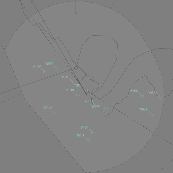
Radisson Pier Helipad
VFR helicopters transit from the Reef to a floating pontoon helipad on the southeastern shore of the CBD, approximately 2nm from the runway 33 threshold. This helipad is referred to as Radisson Pier (YRAP) or simply 'The Pier'.
Prior to issuing clearance to these helicopters, ensure that no conflict exists with other arriving/departing traffic, particularly aircraft departing from runway 15 or arriving on runway 33. Visual separation may be applied between these aircraft if appropriate.
Arriving helicopters should be cleared direct to The Pier, not above A005 and instructed to report on the ground.
Phraseology
YZM is a VFR R44 tracking from Upolo Cay to False Cape, inbound to YRAP.
YZM: "Cairns Tower, helicopter YZM, 5nm northeast of False Cape, A005, for The Pier, received Hotel"
CS ADC: "YZM, Cairns Tower, cleared direct to The Pier, not above A005, report on the ground"
YZM: "Cleared direct The Pier, not above A005, YZM"
YZM: "YZM on the pier"
CS ADC: "YZM"
Departing helicopters should be cleared direct to their nominated tracking point not above A005, and instructed to report airborne.
Phraseology
VTB is a VFR Bell 505 on The Pier, intending to track to Cairns Airport for a landing on the southern pads. A 737 is about to depart from runway 15.
VTB: "Cairns Tower, helicopter VTB, at The Pier, for the southern pads, received India"
CS ADC: "VTB, Cairns Tower, short delay for clearance"
VTB: "VTB"
CS ADC: "VTB, cleared direct to the control tower, not above A005, report airborne"
VTB: "Cleared direct to the control tower, not above A005, VTB"
VTB: "VTB, airborne"
CS ADC: "VTB, track southern pads, report on the ground"
VTB: "Track southern pads, VTB"
VTB: "VTB, on the pad"
CS ADC: "VTB"
Runway Modes
The preferred runway direction is Runway 15.
Circuits
The circuit height is A010. If an aircraft requires a higher circuit altitude, an airspace release must be requested from CS TCU.
Circuit Direction
| Runway | Direction |
|---|---|
| 15 | Left |
| 33 | Right |
SID Selection
| Type | Via | SID |
|---|---|---|
| Jet | AKROM | AKROM SID |
| Jet | All others | RADAR SID |
| Non-Jet | NONUM | NONUM SID |
| Non-Jet | All others | RADAR SID, or Visual (in VMC) |
| Type | Via | SID |
|---|---|---|
| Jet | Any | EAZEE SID, RADAR Transition |
| Non-Jet | Any | RADAR SID, or Visual (in VMC) |
ATIS
Approach Type
| Cloud Base | Visibility | Approach |
|---|---|---|
At or above A030 |
>5000M | (blank) |
Below A030 or |
<5000M | EXP INSTR APCH |
| At night | EXP INSTR APCH |
This allows aircraft to track via the Creek Corridor (see YBCS DAP Noise Abatement Procedures) for runway 15, or via a visual right base (commenced from vectors or the KEEWI Victor STAR), when VMC exists below A030.
Coordination
Auto Release
Next coordination is not required for aircraft that are:
- Departing from a runway nominated on the ATIS; and
- Assigned the standard assignable level; and
- Assigned a Procedural SID
All other aircraft require a 'Next' call to CS TCU.
The Standard Assignable level from CS ADC to CS TCU is:
| Aircraft | Level |
|---|---|
| All | The lower of A060 and RFL |
Departures Controller
When a TCU controller is online, aircraft shall be issued with a departure frequency during their airways clearance in accordance with the table below. If no TCU controllers are online, the most appropriate Enroute controller or Advisory frequency shall be issued.
| Runway | Via | Departure Frequency |
|---|---|---|
| All | All | 118.4 (CS1) |
ACD to CS TCU
The controller assuming responsibility of CS ACD shall give heads-up coordination to the relevant CS TCU controller prior to the issue of the following clearances:
- VFR departures into CS TCU CTA
- Aircraft using a runway not on the ATIS
Arrivals
Aircraft tracking via a visual right base to runway 33 will be coordinated by CS TCU (see Runway 33). All other arriving aircraft do not require coordination.